Modify your 3d printing gcode does not require the 3rd party plugin or software on rhino/grasshopper!
Hello to whoever is interested in this topic! Does not matter that you are an experienced 3d printing specialist or you start to explore the possibility for 3d printing, I am sharing with you a method that you can simply modify the g-code in all perspective. From printing speed to the printing path, every parameter that is required for the printer.
Of course, as I said, this approach does not require the 3rd party plugin or software. You can easily modify and well control your 3d printing path!
Required Software/Knowledge:
for implement and fully understand the article, you may need…
- Understanding the data structure in Rhino/Grasshopper.
- Familiar with the g-code format, At here you can refer to the function of the command.
Step 0. Before starting
The core of the approach is contouring the geometry and extract the points from the contour line. Just ahead up, I do not consider the difference in perimeter and infill, neither the fan speed in this attempt. However, these particular things can be quickly done through editing the text file depends on the printer you have. Following is a quick visualization of what is happening in the grasshopper script.
The best thing in customizing g-code is that it opens all kind of possibility! You can speed up to as much as you want (be careful don’t destroy your printer!), you can extrude extra material depends on your design to enforce the structure or just having fun! (I want to see what will happen!)
In the script, almost everything is editable. No matter the printing speed, path, bed temperature, extruder temperature, flow rate, etc. Of course, it required several tests to achieve a better result.
Step 1. Contouring and Organizing
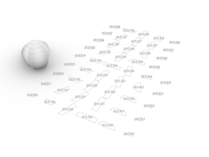
After you import your geometry into the Rhino/Grasshopper environment. You can contour the geometry following the z-direction by using the default contour plug-in. The following step, I had grouped the curves based on their height. Importantly, I organize the curves in a tree structure to make sure that we can always keep track of the curves, which will help us in editing the G0 and G1 movement in the following step. Another reason why we need to do this is that it is easy to sort the curves based on their height and prevent the collision during the printing process.

Step 2. Curve to Polyline
In this step, I am not trying to dig into the rhino definition of the curves, polyline, polygons, etc. In short, I am trying to divide the curve into small segments of straight lines since the extruder can only move in linear movement. (general speaking! )

Step 3. Flow Rate Control
To properly control the flow rate of the material, we need to calculate the length of the printing path. Usually, we calculate the flow rate by length per second or volume per second, depend on which software you are using. However, In some software, you can only control the flow rate based on the percentage or even it does not provide the option. Indeed, it makes sense, because with too much filament be extruded, your extruder might be damaged.

Step 4. Formating the g-code
It is relatively easy to format the g-code in grasshopper since you can visualize the path and text file at the same time. Which is why I highly recommend using grasshopper to edit the g-code in general.
In the script, the most important thing is setting part of the G0 and G1 movement. For those who do not familiar with g-code. Again, please refer to here.
If you are still following, remember that I have divided the curves into different branches based on the height? So the movement between the last point of the branch and the first point of the following branch will be G0 movement. As long as we follow this logic, nothing will go wrong. Therefore, it really matters the printing paths are be arranged in branches before we formating the g-code.
special thanks for Armin Akbari, who also devote to part of the code.

Step 5. The Last Step
Before exporting the text file, we need to set up parameters for the printer, such as the bed temperature, extruder temperature, calibration test, etc. Usually, the information can be easily found on the internet. The following code was an example that I use on a closed-source printer.
;FLAVOR:ZCode

;TIME:0

;MATERIAL:Z-ULTRA

;NOZZLE_DIAMETER:0.4

M109 S260 ;

G90

G21

G28 X Y

G28 Z

G92 X0 Y0 Z0 E0

G0 F180 Z15

G92 E0

T0
After setting up the machine parameter, we can export the g-code file and test on the 3d-printer.
Here is the script that I used for printing in one of my projects. Feel free to leave the message if you have any doubts or you want to correct the things in the article.


Comments are closed.